PIPS Positek Inductive Position Sensing Technology

With the increasing sophistication of electronic controls for mechanical systems to provide both accuracy and flexibility of control, there is more demand for durable, accurate and easy to use displacement sensors. Customers are increasingly concerned about reliability, durability and the associated replacement costs of sensors. They also want sensors that can be easily connected and mounted.
The market for displacement sensors covers an extensive range of technologies, each with their own accuracy capabilities, durability weaknesses and cost base. The range spans simple switching devices, such as limit switches and proximity devices, potentiometers, inductive sensors, LVDT’s capacitive, optical, magnetostrictive, Hall Effect, magnetoresistive and laser based devices.
Coil based sensors provide a good combination of robustness, durability, performance and cost. However, they have also traditionally been complex to install with multiple wiring connections and with separate electronic interfaces for maximum performance. Compared with a potentiometer they have also been quite expensive. Many sensor users would like to be able to purchase sensors with the life and durability of an LVDT but with the ease of use and cost of a potentiometer. The limiting factor has been the high cost of the electronic modules, special materials and the complexity of the coils.
The customer’s requirement can now be more closely met by a technology from Positek which is very simple and compact, offers high performance and can be produced at relatively low cost. The technology is based on inductive coils and features a unique microelectronic interface which provides excellent overall performance.
A range of devices has been developed using the new technology including both linear, rotary and tilt sensors. The range includes standard sensors with linear travels of 10mm to 800mm and rotary displacements of up to 360°. For special applications in fluid power systems cylinder feedback sensors and miniature spool position sensors have been produced. The technology also has the capability of satisfying Intrinsic Safety and Explosion Proof requirements from certification bodies such as ATEX and CSA.
This paper will present this new technology which has won 4 Awards from the United Kingdom Government. The technology incorporates a novel patented technique for the high speed analogue signal processing which offers excellent performance with very simple mechanical construction. This paper describes the fundamental operating principles behind the technology and will also describe how the electronic interface was implemented as a custom integrated circuit. Some examples of products based on the technology including the levels of performance which can be achieved will be presented.
With many years’ experience in the sensors and transducers market, particularly for the automotive and aerospace industries, the engineers at Positek wanted to be able to offer customers in the industrial market displacement sensors which were compact, robust and durable and available at reasonable cost. Positek sensors offer the advantages of a non-contact inductive sensor but with the simplicity and cost effectiveness of potentiometers.
Positek linear, rotary and tilt sensors, are totally self-contained displacement sensors which provide a simple analogue output from a dc supply voltage. They require no separate signal conditioning and are designed to be exceptionally robust and easy to use. A variety of industry standard interfaces such as ratiometric, voltage and 4-20mA current have been designed using a modular approach to simplify the mechanical and manufacturing construction and to provide customers with a high level of flexibility.
It was agreed at an early stage that sensors based on inductive principles offered the best potential compromise between robustness and performance. LVDT technology has proven itself in the industrial and aerospace markets even though it is based on old technology which has several disadvantages. The coil structures are large with very high turn counts of delicate wire and the overall length is up to three times the travel. This adds cost and makes installation difficult. Also, in order to achieve the best performance, the interface electronics unit is often large and bulky, and has to be mounted independently of the sensor. Furthermore, in order to achieve good temperature stability, the electronic modules must be matched to the sensors making the installation even more complex.
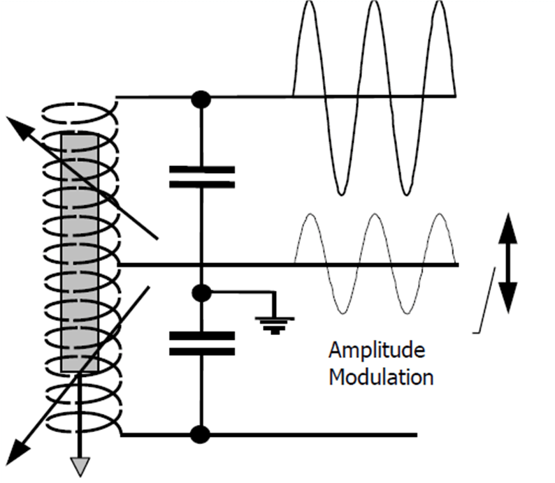
The Technology PIPS (Positek’s Inductive Position Sensors) The PIPS sensors use a primary sensing element which is a variable inductive coil arranged in a simple half bridge. A full bridge resonant circuit is created by coupling two capacitors across the coil. With the circuit driven into resonance by an oscillator, the output is taken from the center tapping. As the relative inductance of the two arms of the bridge is varied the peak voltage of the output signal is modulated, see Figure 1. This is a fundamentally well understood principle.
Figure 1: The Basic Sensor Circuit and Signals
The Positek coil is, however, very different to other inductive sensors in that it uses a coil with very few turns of wire, typically 100 turns. In a linear sensor the coils are wound on a former with standard enamelled copper wire. In rotary sensors the coil is produced using standard printed circuit board manufacturing techniques.
The result is that the coil can be very compact and is very robust. It is possible to produce linear sensors with coils of only 1.5 mm diameter. With only a few turns the coil has a very low inductance and with appropriate capacitor values the natural frequency of oscillation of the LC circuit is set in the order of 1 to 2 MHz. The frequency is not specifically controlled and is allowed to vary as the target moves over the coil.
To change the inductance of the coil a conductive target is arranged to pass over or through the coil and eddy currents are induced in the target which changes the inductance of the coil. The best materials for influencing the inductance are conductive but nonmagnetic materials.
Aluminum and some stainless steels are good examples of suitable materials due to their low cost and very well defined and consistent electrical properties. The target only needs to be thin, 0.1 mm is sufficient, since the eddy currents flow in the surface of the material.
For any sensor the most important characteristic is its ability to consistently produce a stable output signal which is representative of the position of the target being measured. This must be achieved over a wide range of environmental and operating conditions. A transducer coil itself is not the only component that must produce a stable and consistent signal. The other important element in any sensor is the electronic interface which decodes the raw oscillating signal into a signal which can be easily used by the customer. In PIPS this is where some of the most exciting developments have taken place. Consistently decoding a signal which is oscillating at 1 MHz is not easy but with PIPS there has been a significant innovation in the interface circuit which enables it to produce excellent performance at low cost.
The Electronic Interface
The interface circuit produces an analogue signal from the varying amplitude of the signal from the center of the bridge. The interface measures the amplitude of the output signal by taking a sample at exactly the same point in the cycle each cycle.
The main problem is to ensure that the sample is taken at exactly the same point in the cycle even though the operating frequency varies as the coil inductance varies. To do this the decode circuit uses two internal servo loops to align the sampling of the output signal and to control the amplitude of the drive signal.
Figure 2 shows the oscillator drive signal and the timing arrangement for the sampling of the signals. Two switches are connected to the drive from the oscillator and controlled so that they take consecutive samples of the drive signal. Switch B closes first after a delay period A which is triggered by the zero crossing of the signal. The sample taken from switch B is fed into a comparator and immediately afterwards the sample taken from switch C is fed into the comparator.
Figure 2: Drive and Sample Timing Signals
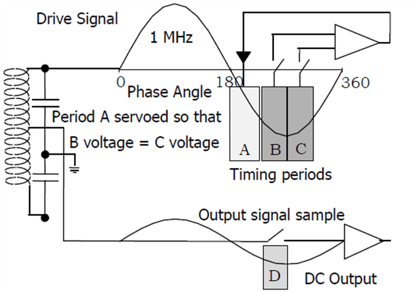
Both the switches are closed for the same duration of about 60ns. Any resulting difference between the two samples is fed back to adjust the delay period A. The servo loop adjusts the timing of the two switches is such that the sample voltages are equal and at this condition both switches are equally spaced about the peak of the drive signal.
There is therefore a stable and controlled timing arrangement which is related to the drive signal and which is used to control the timing and sampling of the output switch D. In addition to the timing of the samples, it is important to control the amplitude of the drive signal. This is simply achieved by comparing the sample voltage B with a reference voltage and adjusting the oscillator drive voltage.
Temperature and Environmental Effects
Most sensors are sensitive to temperature to a greater or lesser degree. With inductive sensors wound with copper based coils and using special high permeability materials, temperature can have a significant effect on the stability of the output signal. The resistance of copper changes significantly and special materials often have nonlinear and inconsistent performance changes. The PIPS technology exhibits fundamentally stable characteristics with temperature. By carefully selecting the timing of the output sampling the interface circuit can be arranged to be insensitive to resistive changes.
Figure 3: PIPS Resistive Rejection Effect
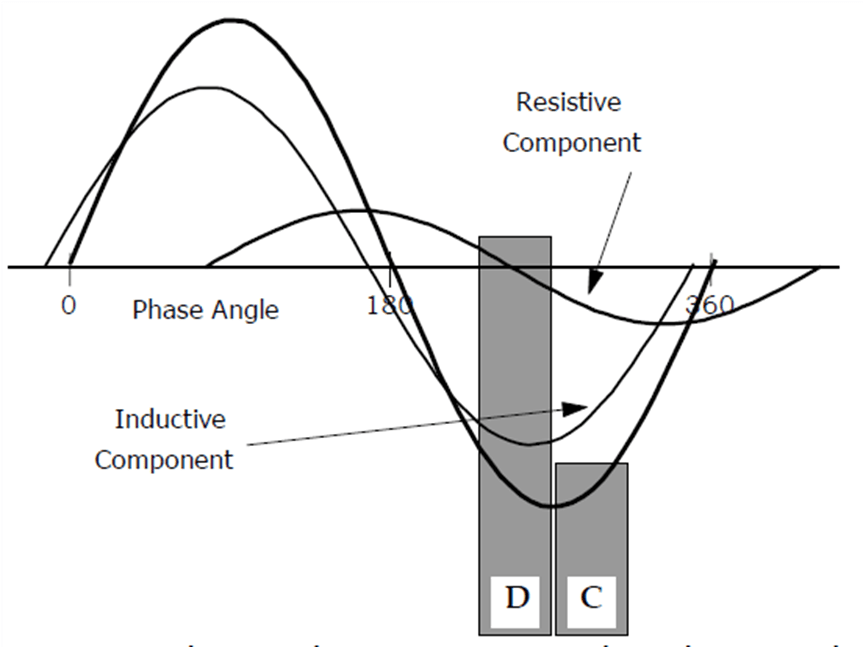
Figure 3 shows the output signal with its inductive and resistive components.
The resistive component is out of phase with the inductive component and the peak of the inductive signal is slightly in advance of the peak of the combined signal. The timing of the output sampling, D, is at the same time as the B sample which is immediately before the peak of the signal, see Figure 3. At this timing the inductive signal reaches its peak value whilst the resistive component is passing through the zero. Therefore, the resistive component of the signal is measured when it is very small and any changes in resistance of the coil are rejected. The electronic interface has a small temperature coefficient and this is compensated for internally.
Implementation of the Electronics
With high resonant frequency of 1 to 2 MHz the sample voltages have to be obtained during a period of about 60 ns. Stray capacitance and leakage in devices become significant when operating at these frequencies and it is not practical to build a circuit made up of discrete components. The only way to implement the circuit successfully and achieve the performance required was to design a fully custom integrated circuit.
A major benefit of an integrated circuit is that it reduces the overall component count and size of the electronics. The reduced component count improves the reliability of the circuit. The complete circuit is extremely compact and has been designed onto a single circuit board, 32 mm in diameter, including full EMC protection. With a small size the electronics may be fitted directly into the sensor casing. Versions are also available on a 17 mm diameter board with EMC protection on an additional board.
The low component count and the elimination of external electronic modules both help to reduce the cost of the sensor and make it easier to install for the customer. The basic interface electronics provides all the control and drive functions from a 5V supply and will produce a voltage output signal from 0 to 5V for the full travel. The interface includes both gain and offset adjustment for calibration and customer adjustment purposes.
Customers in the industrial market demand a lot of choice to suit the precise mechanical and electrical requirements of their application. Common interface requirements include 0-10V output +/-10 (or +/-5)V and 4-20mA loop powered. Lower cost 3 wire 4 to 20mA versions are also available. These options can be catered for by incorporating additional signal conditioning with supply regulation and output amplification in modular assemblies built around the basic interface.
All the sensors using PIPS are available with a two wire loop powered 4-20mA option. This option has been achieved by incorporating a special power supply configuration to power the sensor from less than 4 mA. The 4-20mA option is especially useful in large process control applications where cable lengths between controller and sensor are long.
Rotary Sensors
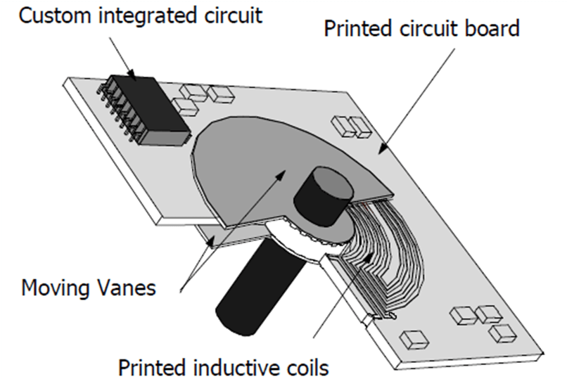
Up till now there have been few rotary sensors which have been able to provide the kind of price and performance of a potentiometer but without the disadvantage of poor durability. Traditionally the only non-contact alternatives to a potentiometer were RVDT’s, resolvers and optical encoders. All of these are relatively high-cost alternatives with their own limitations. With RIPS it is now possible to produce a much more cost-effective device which is compact and has exceptional durability. The construction of the RIPS sensor is shown in figure 4.
The coils are produced using standard printed circuit board techniques and the target which affects the inductance of the coils is made up of a pair of semicircular vanes which are mounted either side of the printed circuit board. The coil structure on the printed circuit board is designed to produce optimal linearity over a large angle. At the present time is possible to achieve good linearity of +/- 1% .
Figure 4: RIPS Rotary Sensor- Construction
The vanes are spaced equally from the coil board and are mounted onto the sensor input shaft. In the design effort has been made to eliminate costly end thrust bearing arrangements and in the case of RIPS the tough printed circuit board takes all the end thrust through a special bearing material applied directly to the board. Control of the input shaft is achieved using either plain or sealed ball race bearings.
The RIPS sensors produce excellent performance over a wide temperature range. Linearity is very consistent between units over a wide angle because of the manufacturing technique employed.
Linear Sensors
A variety of Linear sensors have been produced based on the PIPS technology. Because of the simple coils considerable flexibility is possible in the construction of the sensor.
The flexibility of the coil design and the lack of special target materials create interesting possibilities for designing sensors integrally within machinery such that the actual component can be sensed directly. This often eliminates several components and simplifies the installation of the sensor for OEM designs. An example is within a brake servo system where the position of the servo piston must be known. A LIPS sensor can be applied to measure the piston directly without interfering with the mechanical linkage from the pedal to the piston.
Cylinder LIPS
These sensors are designed for use in fluid power applications in hydraulic and pneumatic cylinders and where environmental conditions dictate a fully sealed assembly such as internal gearbox controls. These sensors are designed with a coil wound on a stiff fiberglass core and sheathed with a high-performance polymer which gives exceptional fluid resistance. The coil and sheath are epoxy filled to produce a robust and pressure insensitive assembly. The basic construction of the sensor is as shown in Figure 5.
Figure 5: Cylinder LIPS P100- Construction
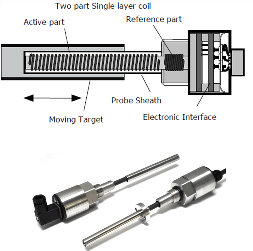
The coil is wound in a single layer with a coarse helix and the pitch of the helix is controlled to give a linear response. In linear sensors the ratio of the overall length to the travel is important. With LIPS sensors this ratio can be almost 1:1 since it is configured with only half of the bridge circuit active. The active coil is wound over the length of the probe whilst the other half of the bridge is a very short reference coil. In some cases, this can be a commercial inductor mounted with the electronics, but for optimum performance, good material and temperature matching, a wound reference coil is used.
The finished probe has an overall diameter of 6.4 mm and the small size of the probe makes it particularly suitable for pneumatic applications where piston sizes can be smaller. The sensors have been successfully applied to a wide range of control applications including ship stabilizers, water jet propulsion systems and high-performance car suspension systems as well as many industrial process control applications in severe environments.
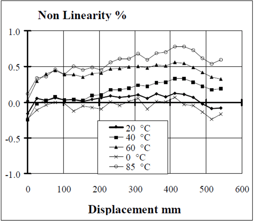
Sensors with travels of between 4 mm and 800 mm can be accommodated with this design. Standard levels of linearity of 0.25% can be produced with ease. By fine tuning the winding profile good linearity can be achieved over almost the full length of the active coil, as shown in Figure 6. For this sensor the coil is only 10 mm longer than the calibrated travel. Temperature stability is excellent over a wide range. The sensor will produce a total absolute error of less than 1% over 0°C to 80°C.
Figure 6: Cylinder Lips - Absolute Performance
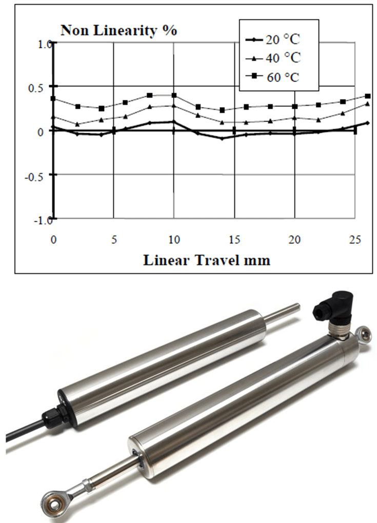
The P101 and P111 sensors are constructed in the same manner as the cylinder LIPS P100, with an outer body tube and target bearings added. The performance of a 25 mm stroke P101 type is shown in Figure 7.
The sensors can be produced with travels up to 1200 mm and are available with a number of options. The sensor can be supplied with rod end fittings or with body clamps.
Figure 7: P101 LIPS - Absolute Performance
Series 103 Stand Alone Sensors
These sensors use an external coil with an internal pushrod as the target. The sensors are provided with an integral bearing assembly and has a reference coil mounted in the electronics section with the active coil spaced along the majority of the sensor. The general construction is shown in Figure 8 and is used for sensors up to 50mm stroke.
Figure 8: LIPS 103 - Construction
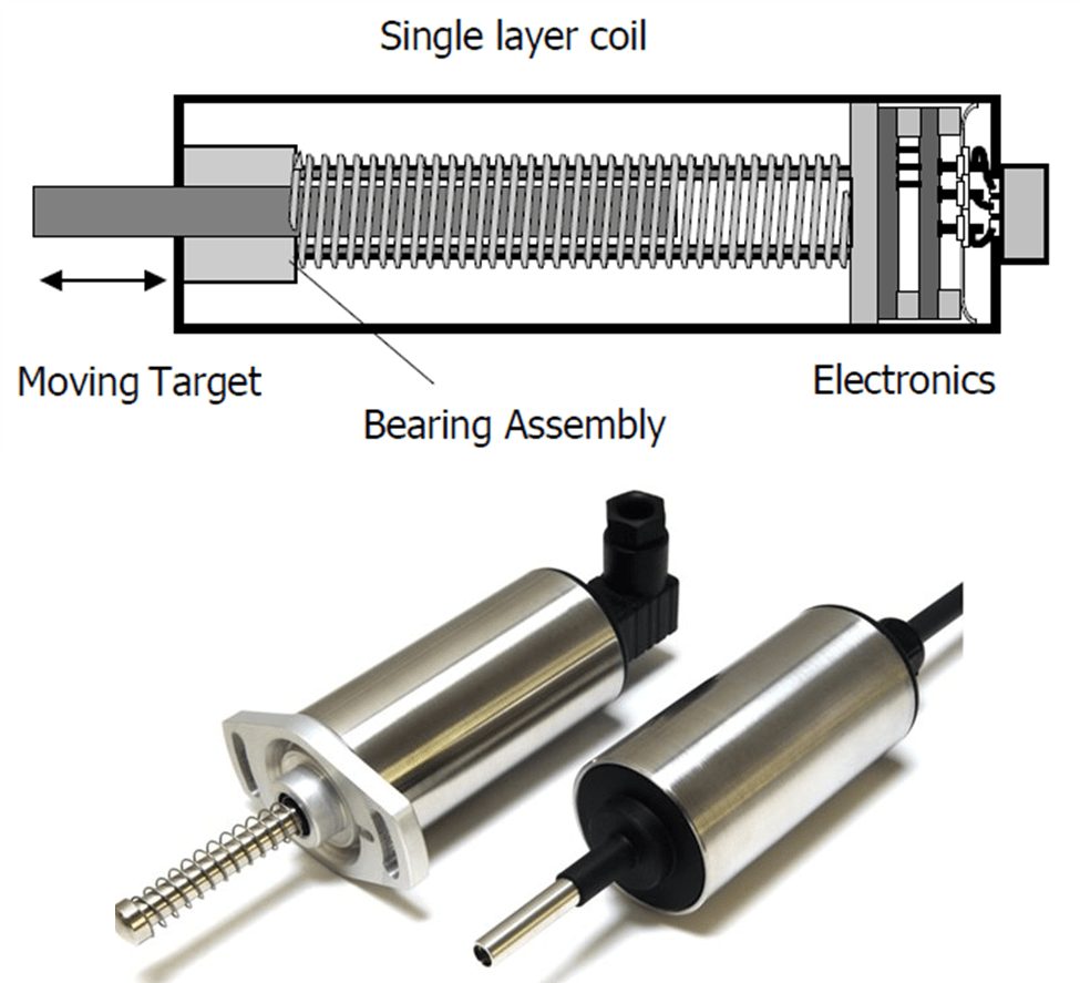
The electronics are mounted in the end of the sensor and the whole assembly is mounted in a very robust stainless steel housing tube. A mounting flange is available.
The performance of the series 103 sensors is similar to the Cylinder LIPS type.
Miniature and Custom Sensors
One of the major advantages of the PIPS technology is the very small coil size which is required. This leads to a significant and exciting capability of the LIPS technology in its ability to produce extremely small sensors for measuring short travels of up to 10 mm. The sensor coil is fully differential and has a diameter of only 2.6 mm. The housing for the coil is a ceramic or plastic tube which has an outside diameter of 4 mm. The sensors uses an external concentric tube as the target.
In the Miniature LIPS sensors the construction is similar to the Cylinder LIPS except that the coil is constructed in two identical parts. In the mid travel position the target covers half of each coil. This gives a fully balanced situation which improves temperature stability at this position.
Figure 9: Miniature LIPS - Construction
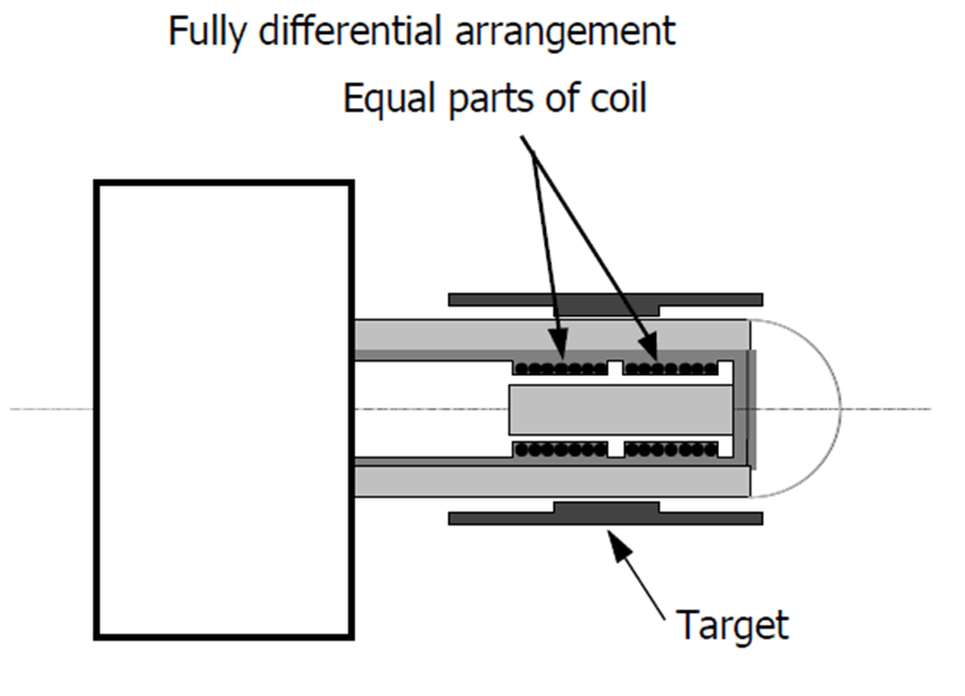
Applications for the miniature series of sensors include positional feedback in proportional and servo valves. The outline of a sensor with a 2 mm travel is shown in Figure 9.
Figure 10: Miniature LIPS - Absolute Performance
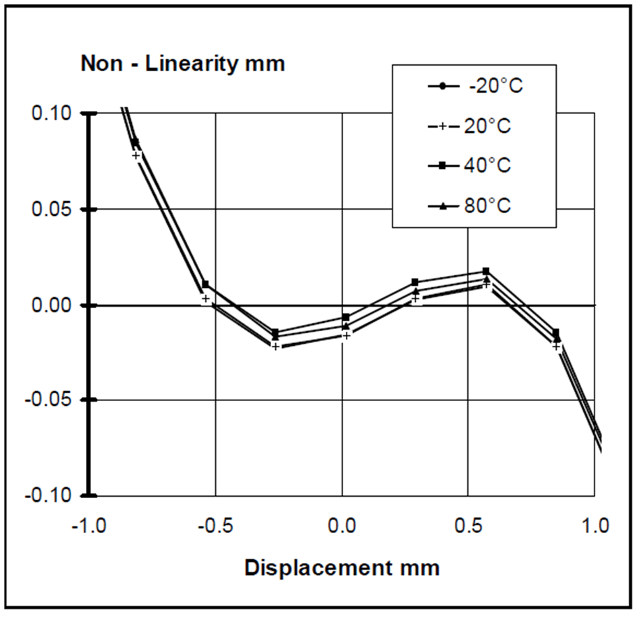
The performance of the sensor is shown in Figure 10. The linearity of the sensor is within 1% for a travel of 0.8 mm close to the midpoint of the coil. The temperature stability of the sensor at this point is excellent with a drift of less than 10 um for a temperature change of 50°C
Intrinsically Safe Sensors
Versions of the electronics have been certified for use in explosive atmospheres. We have ranges of most of our standard designs, ATEX approved for use in Mining, gas and dust atmospheres with extended temperature ranges of -40°C to +80°C.
The certification allows great design freedom for gas and vapor approved devices and some freedom for other environments, giving the ability to create special designs without having to re-certify. Positek holds certifications for CSA, IECEx and ANZEx approved products, for applications throughout the world.
Conclusions
A position sensor technology has been developed which has been successfully applied to a range of displacement transducers. The technology can be applied to sensors which can measure both linear and rotary movements. The new sensors have the advantages of small size and a unique miniature electronic interface which is integrally mounted within the sensor. The sensor performance is excellent and the nature of its operation gives it very good stability with temperature changes. The construction of the sensors is simple and robust which gives good durability and reliability in service. RIPS is a rotary sensor which can provide exceptional durability for limited angle applications. LIPS sensors are a range of devices which can be applied to stand alone applications for travels of 1 mm to 1200 mm and for fluid power applications.
Do you have questions?
"*" indicates required fields

 856-727-9500